Distortion-free close-up stereoscopic photography.
Setting the stereo window
By John Wattie
|
version
31.07.06
- Practical limitations of stereo base, in keystone-free
macro-photography.
- How to take and crop the picture without keystone
distortion
- How to adjust the effective window distance
- Computer stereo is digitised, but so is real life
stereoscopic vision.
- Card-boarding: why individual objects
sometimes look flat in a 3D picture.
- Computer stereo Infinity separation < 0.59P pixels.
- By special request, "hard words"
are printed like so and
definitions are seen by hovering your mouse over them.
Older
browsers may not handle this feature, or may take a long time to work.
- Less important asides or "fine
print" are green
- Links on this page
- [Links] within this web site
- Links to other web sites should open in a new window and are enclosed with
curly brackets:
{ Link }. Just close the new window to get back here
Practical stereo base in close up
stereoscopy
The maximum "stereo base" in macro photography is given by the
Davis modification of the Bercovitz [formula.]
If you are trying to be "professional" and make
3D pictures which do not give people headaches, there are some limits to what is
possible using the formula.
A Holmes
Card, or the common slide formats (RBT, Stereo realist etc) are all square or close to it. This
section will explain how to get a square or vertical ("portrait") macro stereo without
"keystone distortion"
-
The "requirement" to avoid any keystone distortion
limits the stereo base, because you cannot ""toe in"".
-
Lack of toe-in
means the stereo pair will always have an "infinity window", which has to be
corrected later.
-
For cameras using an oblong picture, the maximum possible stereo
shift demands a landscape format (horizontal oblong).
-
Once it is cropped for an effective stereo window in front
of the subject matter, the landscape format becomes
a portrait format - one of the many paradoxes of stereo photography.
-
Convergence is not always obvious. Beam splitters for
example include toe-in, but often have a small stereo base, so the keystone
distortion is small.
-
Remember horizontal differences are allowed between stereo
pairs, but vertical differences must be minimal.
(x parallax is OK but y parallax is not. Keystone
distortion causes y parallax.
This the classical statement about parallax, but is not quite right. If you photograph a vertical flat surface which is
running away into the distance at an angle, there is a small change in Y parallax between the two images even if you take great care to only move the camera sideways on a micrometer controlled stage. I will illustrate this later by photographing a grid - or you can do it yourself and save me the bother).
How to take a macro stereo pair,
perfectly windowed,
without key-stone
distortion.
The John Wattie method,
involving no measurements or computation.
Although the author does all this "in his head," the procedure essentially means:
- You set up a picture frame (made of card-board, for example) in front of the object to be photographed. You really only need the two vertical edges, since height of the frame is adjusted in post-processing.
- The camera is aimed so the picture frame is displaced to the left in the digital camera's focusing screen (or SLR viewfinder...)
- Take the right picture.
- Now slide the camera very accurately to the left, in a horizontal plane, without toe-in, until the picture frame is on the right of the view-finder.
- Take the left picture.
- You now have a "correct" 3D base (or at least one which works very well).
- You have set the stereo window precisely where wanted, in front of the object.
- There is no key-stone distortion.
- You have not bothered your head with any measurments or computations, the whole procedure is automatic and just works.
- Post-processing of the stereo pair is now done in the computer.
Taking a portrait macro
picture in landscape format, then cropping for stereo window.
The example photograph is the discarded "skin" (exoskeleton) of a cicada, on the floor of a pine forest. This stresses that stereo macro-photography in the field is easily done by this method. It is not set up in a studio.
{Click here for the big version}
The final format of the stereo pair is decided in Photoshop.
(U Stereo - do not go cross-eyed on these pairs!)
3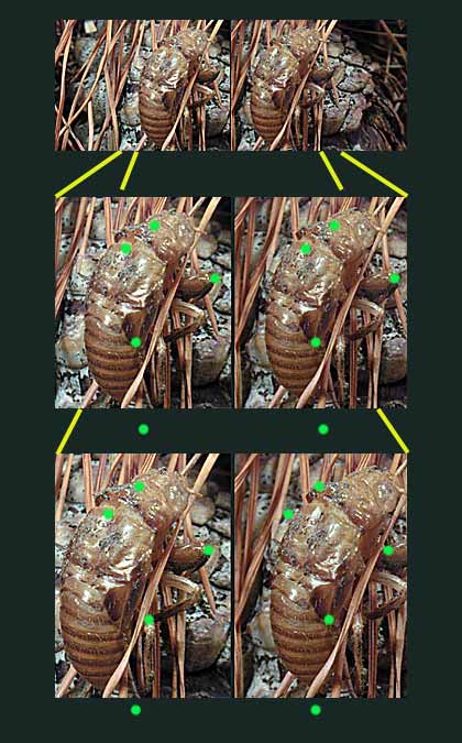
The final images are portrait format, but a landscape format camera was used.
-
The left image required the final, "portrait shape" to be set up on the right of the landscape format view-finder frame. (See the top pair)
-
The camera was slid sideways along a straight line, to the right, with no toe-in.
-
The right image moved across in the camera view-finder until its vertical oblong shape was on the left of the frame.
-
Any further shifting means the insect exoskeleton goes out of the frame, so that is the limit.
|
Taking and post-processing a macro stereo photograph, with no mathematics |
|
During post processing,
the lateral bits of both pictures
are cut away to make the
desired stereo window. (U stereo).
By cutting more away, the subject gets deeper in the window,
as shown by the two examples.
The shape of the stereo pair changes as the sides are cut away, becoming "portrait" instead of "landscape" This is not so bad: stereo pairs fit better on a computer monitor or in a Holmes viewer when they are "portrait".
It is impossible to do much with the two middle
edges of the stereo pairs. Cutting here loses vital parts of the picture. The middle edges
must be properly set up while taking the macro stereo.
The green dots are separated by the same distance as the two
windows. They
help you see which parts of the subject are behind the window frame.
The window for the bottom pair is in front of the
exoskeleton. All green dots are in front.
The middle pair has the exoskeleton protruding through the
frame, so the dots are inside the skeleton.
Both versions should be acceptable, since nothing at the
edge of the picture lies in front of the window.
- Some people prefer the middle version, since it has less "edge stereo failure".
- Very traditional workers may only accept the bottom pair, where nothing at all lies in front of the window.
- Objects poking through the window are not much of a problem for computer stereo or stereo seen in an optical viewer. It is a valid objection for stereo viewed by projection on a screen. People sitting behind the ""ortho-stereo seat"" see a smaller picture with greater depth and may be disturbed by objects poking "too far" out of the screen. (Stretch).
Choose the method you personally like, but the middle version is much easier to arrange, so that infinity parallax is not excessive and edge stereo failure is minimal. It is obvious which I prefer for free viewing or a Holmes card, but projection stereo is a different matter! |
Taking the pictures
There is no need to measure the distance to the subject (which could result in breaking a delicate object or frightening an insect away.)
This procedure is best with the two camera directions operated by screw threads, rather like a mechanical stage on a microscope.
(For example, 2 Manfrotto {micro-positioning} plates, or see the {review} here).
- You adjust the magnification to the desired value as marked on the macro lens.
- Move the camera back and forwards to focus it.
- Then move the camera sideways between two exposures, by the distance B (stereo base). You could compute and measure B, (by the Boyer [formula], for example) but this automatic method avoids that.
This is a very sensible way to focus a camera close-up. Changing the "focus" on a macro lens when it is racked far out is really changing the magnification and does very little about getting the focus correct. Those of us who have worked with extension bellows know that well.
With a small digital camera (like the Nikon 4500), the lens is set to the "macro sweet spot", which has a flower symbol. Then move the camera back and forwards. Final adjustment is done with the zoom function, taking care to stay in the "sweet zone," with its symbol. Final focus is auto-focus, but there is a bad tendency for the camera to auto-focus on the wrong place in macro work, even when using the moveable focus points.
Manual focus is not easy on the small viewing screen of a 4500. This was the main reason I shifted to a Canon SLR. A 105 Macro lens was purchased to provide better than 1:1 magnification (1:1.6, because of the magnification factor of the small digital chip). Working on the floor of the forest, a right angle view attachment had to be purchased.
The macro 3D method described here works just as well on larger format as it does on small digital cameras. There is no correction for film format. It really is a computation-free process.
Depth of field correction
Two micro positioning plates are better than one. The stereo base is set up with one plate. The other is at right angles to the base, in the line of focus. I use a big Manfrotto plate for focus with a smaller, lighter device mounted on the Manfrotto, at an accurate right angle, for the stereo base. Micro-positioning plates for cameras are available with two movements at right angles, much like a mechanical stage for a microscope and that would be good too. (See image on the left). It is then possible to:
- Set the magnification (lens extension or zoom)
- Focus with the in-line positioning plate (focus plate), winding back and forwards.
- Take a series of pictures, varying the focal point through the subject by winding the focus plate. Overlap the depth of focus zones. You may have to vary lens "focus" as well, because each picture must have the same magnification and moving in on the subject makes it bigger. Combining plate winding and focus can be a frustrating business and encourages the operator not to have too much depth in the picture!
- Use manual exposure, so all images have the same brightness.
Some workers say it is best to use f8, to avoid diffraction effects from big f numbers and correct for the resulting shallow depth of field in post processing. I like to work at f45, when not stacking pictures, so this is a new concept for me.
- Wind the transverse, stereo base plate for the correct stereo base.
- Take another series of pictures by winding the focus plate, just as for the first set.
- Finally, fuse each set of pictures with image stacking software, to produce immense depth of field for each of the stereo pair.
This is possible in Photoshop, but is better in dedicated stacking programs using wavelets for assessing focus. Better still is a program allowing digital subtraction of an out of focus white card, to remove dust or dropped pixels, which cause trouble during stacking. The white card picture also allows colour temperature correction in Photoshop.
Precision is difficult using camera toe-in unless the camera is mounted on the focus plate. The focus plate can then be rotated on the stereo base plate - with some frustration. (Yet another reason to avoid camera convergence in macro photography). Camera rotation is possible with two separate plates, but I have never heard of a commercial, bi-directional, micro-positioner providing toe-in.
- With internal focus macro lenses, it may be better to change the focus on the lens, according to John Hart.
http://www.crystalcanyons.net/Pages/TechNotes/3DMicroMacro.shtm
|
More gentle macro 3D depth
If you want more gentle stereo, shift the camera less, so that you are shooting through a square window rather than a tall window.
You could even set this up precisely in your view-finder with a moveable piece of paper:
- Arrange the vertical strip of paper to cover all but a square of the oblong view-finder, on one side. (Best with a digital camera having a rotating screen - the Nikon 4500 is ideal).
- Take a picture
- Shift the paper to the other side of the view-finder screen, so your viewing square shifts sideways.
- Wind the camera sideways and precisely on the micro positioning plate until the "same" picture you took before is seen again in the finder
- Take another picture
- Done - you have a perfect macro stereo pair!
This little scrap of paper is much more practical than setting up a physical picture frame in front of the subject, but it is optically equivalent to doing that.
(In practice I do not use the paper mask, it is very easy to do all this in your head.)
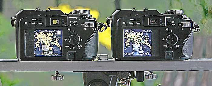
- Sony V3 has a wide stereo base of 13.5cm when two are set side by side.
- Cardboard strips mask the viewing windows to square, as shown.
- Set the cameras on maximum telephoto (X4)
- Move them back and forward until the image in the two masked windows is the "same."
- You can even view them in stereo using a Pokescope.
- The images you take will have a very pleasant stereo base.
- Note this only works when the Longest distance is less than twice the Nearest.
- Twinned Sony V3 are not able to take macro stereo, 2300mm is the closest this rig can get.
- Bigger magnification is possible when one camera is used, but you are then back to the single camera shift technique.
- A stereo close-up with a base twice the inter-ocular distance is not intuitive, but the Berkovitz and Di Marzio equations predict it will work - and it does.
The stereo base from this method varies, but is very close to the Di Marzio close up formula:
B = N/15
Where B is the base and N is the nearest distance.
In this example, B is nearer N/17.
- Notice the Focal length does not come into this formula because it canceled out during the derivation
- That is why you set the lens to telephoto, to get maximum magnification possible when the cameras are so far from the object.
Here is an anaglyph of a tuatara using exactly this set-up.
|
Hypo-stereoscopy
If you want a landscape format stereo pair viewed side-by-side, there will always be
a limitation on the length of the stereo base. But the result with a short
base is still 3D.
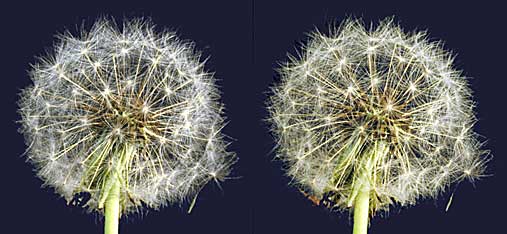
In fact the more gentle stereo of this example [Tarata
flower] is preferred by many people. They say hypo-stereoscopy is another
word for macro stereo.
X
stereo X stereo
The contrary view is: If you look very closely at a flower,
then you are using considerable stereo angular parallax of up to about 12 degrees, and
the restrained stereo in this example is not what you would see.
The argument for just a little camera convergence
-
If you take photographs
from the start in portrait format (vertical oblong)
there is not enough picture to cut away. So you have to toe in - which
is "forbidden!".
-
However, if you use cross-eye viewing or prism viewers which diverge
your view (Pokescope, Holmes), they also cause keystone
distortion. The nasal sides of the stereo pair are more magnified than the
lateral with these viewing methods. Toed-in stereo projectors do the same.
-
A little bit of toe in while taking the
picture can help correct for keystone distortion in the stereoscope!
-
Rigid application of the "no
toe-in law" means some excellent [macro
stereo methods] are "forbidden". This includes beam splitters,
which often have toe-in as part of the optical system.
- Experiments show up to two degrees
of toe-in is not noticed as distortion by most people viewing the result. Two degrees is just the right amount for standard stereo slide mounting, where the window is set at 2 meters to infinity.
- Toe-in is equivalent to using a much wider stereo base and in the macro world it is vital to keep the Longest distance much less than twice the Nearest or the background will be impossible to fuse.
Sliding camera mounts for: 2 degree toe-in, macro stereo.
See above for how to use a shift lens for wider format stereo - but not everybody wants to own a shift lens.
A plywood method
You can easily set up for toed-in
portrait format macro stereo, or
wide, landscape format, macro stereo
with a sliding box to carry the camera.
- This box, holding the camera, is going to slide on a piece of plywood.
- Have two lateral wooden strips, glued to the piece of ply-wood, set up at 2 degree angle to each other.
- These strips decide where the camera stops when slid sideways, so you have to leave a decent gap between them.
- Put the plywood on the table.
- The two angled stops would, if projected, meet at the object being photographed.
- Slide the plywood and its stops backwards and forwards on the table, until the camera view-finder shows the foreground is centred the same in both pictures.
Your piece of plywood can be set up on the floor of the forest, but I soon got sick of it. You may well want to work from a tripod to make your macro panorama shot.
A tripod method
Turning 2 degrees using the micro plate mounted on a pan head proved too cumbersome and not even good geometry since the camera not only turned but also swung in on the end of the lever formed between the pan head axis and the camera axis.
The turn should really be made around the front nodal point of the macro lens, not the camera base. You can set that up by mounting the camera on a flash bar to move it back from the axis of the camera mount, bringing the lens nodal point over the micro plate mounting screw. Fortunately a Nikon 4500 does not need this refinement, but a digital SLR with a long macro lens does.
- This displacement of the camera away from the nodal point will vary depending on how much you have extended the lens (which determines the magnification). The long slot down the middle of the flash bar allows for that adjustment.
- Measure or mark the correct stereo base, using the piece of paper to make a square format on the view-finder, as described above (or do it in your head). This square is too narrow for the panorama format you want, it is just a measuring move.
- Slide the micro plate back to half way between the two marks and aim so the camera covers the wide format you want.
- Now wind the micro plate to the left mark.
- Loosen the micro-positioning camera mounting screw and swivel the camera to the right until the viewfinder shows the picture you want again. Don't bump, jar or twist the micro plate. (Easier said than done).
- Tighten the camera screw and take the left shot.
- Now wind to the right mark.
- Loosen the camera screw, swivel to the left until the view is the "same" as before, tighten the screw and take the right shot.
- You now have a macro panorama with toe-in.
Since you measured using a square format and not a narrow, portrait format, the stereo base is "conservative".
You could actually take the left shot and then turn the camera while measuring the toe in, but 2 degrees is a bit small and fiddly to set up. Now slide across to the right until the picture you want once again fills the format. The ideal would be to manufacture a set of stops to give you the 2 degree angle when turning the camera on its mount. I need a tame engineer!
Or you can just mount the camera on the micro positioning plate, without the flash bar and make the stereo shift bigger than measured. This can be done with mediocre precision by measuring before hand how much extra shift you will need to keep the camera lens at the correct separation after toe-in. It will vary depending on how far out the lens is racked (in other words with the degree of magnification). I confess this rough method has been used by me several times.
Do not use a ball head on a rotating base under the camera (as made by Manfrotto). Very tempting, but if the ball head is not at right angles to the plane of the stereo base, there is rotation of the image, which is very hard to correct later. In fact if the ball head is pointed down more than, say, 30 degrees, the rotation is so severe it is nearly impossible to fix. The ball head should be on the tripod (or mounted on the base plate, on the ground). The micro-positioning plate is on the ball head and the ball is only used for setting up the shot. Rotation should be on the stereo base micro-positioning plate, as described above, and then there is no image rotation to worry about.
You will be able to see the toed-in stereo quite nicely in a stereoscope, but the author prefers to apply keystone correction, during post-processing in Photoshop, using Transform commands.This allows for projecting the pair and for making an anaglyph (yuck) which does not look too out of alignment. Once this is done, the 3D stereo actually looks better, probably because you have solved for eye-strain. It is much easier to make these corrections if you have taken the pictures precisely in the first place. If you are making 35mm slides, then precision is most desirable, since the Photoshop tricks are not easily available. (You have to scan the slide, adjust in Photoshop, then ideally get the digital file turned into a slide again. This is the process followed here for Eric Scanlen's orchids, but so far we have not returned them to slide format.)
Now, how are you going to view your wide, landscape format, macro stereo pair?
Answer: Use an over and under mirror viewer. If you said "make an anaglyph" - oh dear. There are lots of anaglyphs on this web site, but the author just did it for the multitude who cannot see stereo better...
Where can you get all these micro-manipulators? Here is a link to one place with more gear than you could ever want, at a price mind you. Despite the range, they do not have a precision, rotating, micro positioning plate, but as far as I know this is an invention of the author. To see it there would be delightful but also a disappointment! They get pretty close with a pan head and camera-offset mounts for the lens nodal point, but not quite the right stuff for stereo macro panorama. I currently favour Manfrotto micro positioning plates, but the world is full of other great toys. (The item illustrated above is from yet another web site, but is not what I use!) ~{;-)}
Effective Window
distance (e).
Macro stereo is not orthostereoscopic unless the window frame
is adjusted to effectively lie at the same distance as the closest part of the
original scene. Normally this is not done. Precision is not even possible, because different people have different inter-ocular distances.
The
window is nearly always set up at a comfortable effective distance (e) for the eyes.
The depth range in the macro stereo pairs are made to fit in nicely from the
effective window distance (e) to stereoscopic infinity. This means the pretty insect is seen
as if it were 2 or 3 meters away, which is comfortable (at least for U stereo).
The most distant part of the close up scene is set at "infinity" even
if it were really just a few mm away. Since humans get little 3D information
from the degree of eye convergence, this distant window seems fine.
As noted in the [physiology
section], 3D information comes from small parallax differences analysed in
the brain. In fact the optic cortex neurons are "hard wired", in
alternating stripes fed from each eye, to measure small differences, but not big ones. The
parallax seen without diplopia is called a Panum zone.
Big parallax
differences cause double vision (diplopia). The big differences are corrected
to remove diplopia, by varying eye convergence, then 3D is built up again for
objects whose parallax is only slightly different from the new convergence
point. This is responsible for the paradox sometimes quoted by physiologists
that objects converged on are not seen in 3D because they have no parallax
differences! (The author thinks this is a silly statement rather than a
paradox, but he is an iconoclast).
Diplopia outside the Panum zone shows up well in the green spots set at stereo
window level on the [3D picture] of an insect
exoskeleton. If you look at the pine cone behind the skeleton, the green spots
are double. If you look at just one of the green dots, then all the dots are
seen single because they are all at the same convergence distance. The
green dots are in the same Panum zone. They are said to lie on the same
horopter.
There is some evidence stereo
perception is greater if the eyes are converged. For example, some people
think they see greater depth using X stereo than U stereo on the same
stereo pairs. Frequently people say X stereo makes things look smaller and
deeper. Experts on stereo seem to lose this impression as they become quicker
at adjusting their eyes for free stereo vision. There are lots of chances to
test the proposition on this web site, where both U and X stereo pairs
are often given. If you think depth impression is greater with convergence,
then all the more reason to use close effective windows when masking stereo
slides. So read on!
Close stereo window
A close stereo window is required if far distant objects and
near objects are included in the one picture. Such extreme 3D may not be a smart
move since it causes diplopia and stereo failure from "monoscopic areas",
including "edge stereo failure"
. This objection to extreme depth is less
significant in three situations:
-
If there is a gradual shift from near to far objects.
-
If the near object is full-width horizontal and so does not cause
monoscopic areas.
- If "falling frame"
stereo windows are used
Calculation of stereo window for 3D pairs
The correct window size for
any desired effective or apparent window distance (e) of a stereoscopic pair can be computed.
t
= i - g - iV/e
t = width of the stereo window (vertical height is not significant in stereo.)
i = Infinity separation set up on
the stereo pair.
g = gap between the two pictures of the stereo pair.
V = focal length of the stereoscopic viewer.
e = effective distance of the stereo window from the observer.
(Formula derived by the author from simple trigonometry).
|
i: It is no use taking the observer's inter-ocular distance
for this formula because
it is so variable, although strictly that is what should be done, but only if
the stereoscope has variable inter-ocular spacing adjustment. In other words it
is too hard and rather pointless!
The Brewster principle, of magnifying lenses set at
a spacing of i in lens stereoscopes, overcomes the problem of people having
different inter-ocular distances. The lenses divert the visual axes for each eye laterally, by just the right amount to always end up on the infinity distance and focused for infinity.
| {http://www.undersea3d.com/}
Mark Blum makes magnificent macro stereo pairs. Any
stereo enthusiast should purchase his books.
Applying the above formula to his book "bugs in 3-D", I
found this range on his various pictures:
|
window
width t = 61 to 63mm
infinity separation i = 67 to 82mm
gap between prints g = 2mm
Viewer focal length V = 200mm
"window distance" e = 3000 to 4000mm (computed). |
The infinity separations of 67 to 82mm are higher
than usually suggested for free-viewing or non-diverging stereoscopes, especially if children are to look at the
pictures. However, the isolated 82mm separation on just one pair was for a
distant object seriously out of focus and not a significant part of the
scene.
These settings are fine for children using a Holmes
viewer.
Blum's publisher cunningly built a stereoscope into the book, with
200mm focal length ordinary lenses. They follow the Brewster principle by having 80mm
separation and so children have no problem seeing Blum's book in 3D, since
it is optically the same as a Holmes stereoscope.
|
Masking 35mm slides to make the window closer
(reduce e).
Three methods are suggested, one of which is useless, based on the author's
apparent window distance formula. Plus a fourth "cheating" method.
t = i - g - iV/e
1) Mask the frames from the outer edges (reduce t)
Consider working with full frame stereoscopic 35mm
slides, each of the pair mounted separately in a standard 2x2 slide mount
(50x50mm).
They are to be viewed in a stereoscope with 50mm lenses.
The slide mounts are fixed in the viewer 12mm apart, which makes a gap of
28mm between the two adjacent picture edges. This separation cannot be varied.
It makes the separation of the slide window:
28 + 35 = 63mm
This gives an effective window just in front of "standard" stereo photography
subjects, where nothing is photographed closer than 2 meters.
Say we want to set up the window closer than the usual 2 meters. Let us
drop it to 1 meter. |
infinity
separation i = 65mm
gap between mounts g = 28mm
viewer focal length V = 50mm
"window distance" e = 1000mm (1 meter)
width of each picture t = 33.75mm (computed)
Since the window width in a standard 35mm slide mount is
35mm, to get the window as close as 1 meter means the outer sides of the
slide mount aperture will have to be masked.
The mask width is:
35-33.75 = 1.25mm
The window separation is now:
28 + 35 - 1.25 = 61.75mm
(instead of 63mm for unmasked slides) |
|
The more we mask the outer sides of the slides, the closer the apparent window
comes and the picture format changes from 'landscape" to square to
"portrait".
|
2) Increase i
Move the
two pictures apart in their frames, showing more of the middle section.
(Increase i.)
Generally it only
works with toe-in pictures, since stereo pairs taken parallel have a big
problem with loss of objects from the middle section of each picture. This
method increases the infinity setting and leads to a stereo pair
impossible for smaller people to view. A Holmes diverging view
stereoscope gives more scope for increasing the infinity separation (i). However, this method is classed as poor and useless.
The author's method to avoid key-stone distortion, but retain a
close effective window, is to use a shift lens
camera in an unexpected way. The lens is shifted opposite to the stereo shift.
-
The
usual way to use a shift lens for stereo is to keep the camera still and slide
the lens sideways for each picture, left then right, giving two images from different positions on a horizontal plane and absolutely no keystone distortion. But the useable stereo pairs are "skinny" (no width to them).
-
The method for close windows means sliding
the lens the "wrong" way and then shifting the camera more than the
stereo base so the final lens separations are the true base.
-
I have since read the Stereo Realist
camera has a small amount of lens shift built in, so although the author
thought it up independently, it is far from an original idea. If I keep on reading instead of experimenting, I will probably find nothing
on this web site is original, but that is hardly the point of the
exercise! I am not sure what is the point - just getting my thoughts in order I
suppose. Another version of a Blog.
3) Reduce g
Keep the slide mounts the same size but bring them closer
together. (Reduce g). This way the infinity separation, which is too wide on wide-base, close-up stereo, is restored to a useable value for viewing.
Moving the slides closer is usually impractical, unless you
have a viewer or projector in which the gap (g) can be changed.
-
In projection stereo it is considered bad practice to
change the slide separation during a show because it drives the audience to
distraction. However, this is fine for experimenting.
-
Slide stereoscopes do not allow gap
adjustment, unless home made with that rarely seen feature incorporated.
-
Over and under print viewers are ideal for practicing gap
variation, by just sliding one of the prints sideways.
|
|
|
If the stereo pair are permanently mounted as a pair for
projection or viewing, then there is the possibility of reducing the separation
between the two windows.
-
In a projector, there is a limitation caused by the small
field of even lighting from the condenser lens.
-
Some optical viewers have a fixed built in window and they
will not permit this method either. It really boils down to home-made
systems.
-
Using 6x6cm standard slide mounts, you have to overlap the
mounts to get them closer together. With cardboard mounts you can even stick
the overlaps together with glue to quickly make a fixed pair.
Taking the pictures for close spaced, full width stereo pairs
often means "breaking the law" because with most rigs it only works by
using toe-in.
|
4 Transform the images in Photoshop
This is a real cheat. It can save a pair in which the infinity separation is too big. Squeeze both images sideways. The picture is deformed: objects become taller than they are broad. If it is not too excessive, you can even get away with it. This brings the infinity points closer together and you can fuse them nicely!
| This flower picture was taken " landscape" and converted to
" portrait" by masking
the edges, There is not any toe-in (convergence of
optical axes) meaning no key-stone distortion.
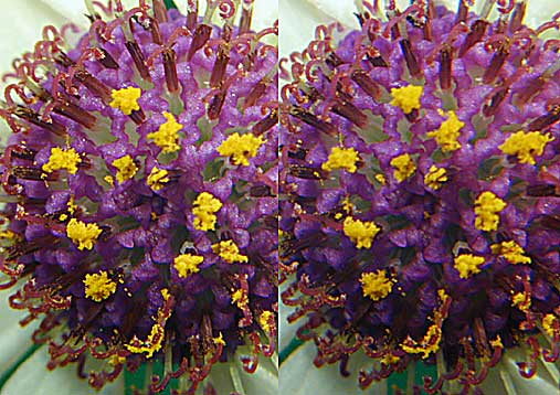
X stereo
Portrait format stereo pairs are
ideal for parallel viewing stereoscopes.
-
Mounted as 35mm slides, you can
arrange the effective stereo window (e) to be almost any distance, by
using the above formula.
-
The original Holmes format is
square, but when printed on 5x7 cards, portrait stereo is readily
visible in a Holmes stereoscope, especially if it has the Thorpe
modification.
|
Infinity
setting, field of view and magnification.
When setting up computer stereo it is easy to forget about the infinity
separation. But just how do you measure infinity separation on computer stereo
pairs when computer screens come in all sizes? Here is a suggested solution to
that problem.
-
With cross eye viewing (X stereo) any infinity separation
can be fused.
-
With parallel viewing (U stereo) an optical device is used
(Pokescope or Wheatstone viewer etc) and the infinity setting can be
adjusted with the instrument.
-
With anaglyph viewing the infinity separation is important,
but it is different depending on the size of the computer monitor and its
settings. A picture looks smaller on 1024 x 760 pixel screen than on a 800 x
600 pixel screen. So the infinity separation will be greater on an 800 pixel
screen than on a 1024 screen by 1024/800 = 1.28 times.
This would be a difficulty, except for a fortunate peculiarity
of humans. Usually with a big picture people sit further away so as to
adjust the horizontal angle of view to about 40 degrees. This was first
discovered by watching where people stood to look at pictures in an art gallery.
Kodak did a number of formal experiments with different print sizes and
confirmed the observation. The standard lens for a
film format is based on this tendency for humans to like pictures 40 degrees
wide. (The preferred angle of view is often quoted as 45 to 50 degrees, but that is
the diagonal across the picture, not its width).
-
For example, a 50mm lens on a 35mm camera has a horizontal angle
of view computed by:
2 (arc tan (35 / 50*2)) = 39 degrees
-
An 80mm lens on a 60mm camera has a horizontal angle of view
given by:
2(arctan (54 / 80*2)) = 37 degrees.
-
(The width of the two common slide formats, 35mm and 54mm, are after they have been put in
standard slide mounts for viewing or projecting. This is less than the camera
gate width.)
This sub-conscious tendency to choose a roughly
40 degree picture is fortunate. As the viewing magnification of a stereo pair is
varied, by sitting closer or further away from the screen and ending up at 40 degrees, so the infinity
separation, measured as an angle, remains constant.
In my opinion, the
liking for 40 degree pictures comes from hard wiring in the brain, which demands
a stable base for building up a high resolution impression of the world. Only
the central part of the retina (the
fovea
) has high resolution. We cannot see a photograph at high resolution all at
once. Radiologists reading X-rays know this. Unless a subtle abnormality falls
on the fovea at some stage while scanning the radiograph, it will be missed. A
scanning sequence has to be consciously worked out by the radiologist if he is
to stay in business.
If the head is still and only
the eyes move, they comfortably
cover a 40 degree view angle. Any more than about 40 degrees and we prefer to turn
our heads to concentrate attention on objects at the edges. Neck muscles,
when turning the head, do not have such precise
proprioceptive
feed-back as eye flicking, which is
happening all the time in
saccades.
Since stereo is seen by brain computation, it helps a lot if the head is kept
stable.
If the stereo pair is printed for viewing in a
stereoscope, then the infinity separation has to be right for the stereoscope.
-
In a
simple magnification viewer the infinity separation is the inter-ocular distance,
i (65mm
usually).
-
Some workers prefer a 62mm infinity separation to suit smaller
people, like children.
-
Infinity
separation is 80 to 90mm in a Holmes viewer, which uses diverging prism lenses.
60x60mm medium format as a
stereoscopic standard to compare with computer stereo.
35mm slides are too small for the very best stereoscopy.
Even in slide mounts they are widely separated for viewing in a stereoscope. This means a lot of potential picture area is not
used and the pairs have to be magnified more to get the ideal 40 degree viewing
angle.
|
|
| (However, 35mm format sort of works for
stereoscopic panoramas, but only when viewed in a medium format stereoscope. Stereo with a Horizon camera for example is possible with a
medium format viewer. Over and Under stereoscopes are much better for panoramas
because bigger pictures can be fused. Wide prints can also be fused in a
large photogrammetry mirror stereoscope.) |
|
60x60mm slides are cropped to 54mm wide when mounted
in standard medium format slide mounts. 54mm pictures are perfect for
arranging a 65mm or 62mm infinity separation.
The effective window distance can be changed by
varying the gap (g)
If the full format of 60mm square is used,
rather than the masked format in standard 54mm slide mounts, there is less
room for gap variation.
|
 |
|
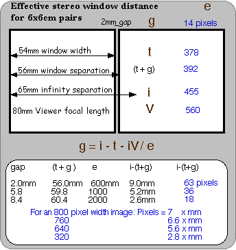
For an 80mm direct view stereoscope a 2mm gap is
good, giving a 62mm window separation. With 65mm infinity
separation, the effective window distance is then 1750mm (5.6 feet).
Stereo pairs are set up on a computer the same
way as 60x60mm format pairs, with very little gap between the pictures. This
means the diagram for medium format square slides can be shown on the same
diagram as computer stereo. |
Digitisation of the stereo depth.
No surprise that depth is digitised on a digital computer screen, but
here we explore the limitations that result from that.
Computer pairs printed from a computer are also digitised in depth, but when done at high
resolution (300 dpi) there is not much problem.
Most of the stereo pairs on this web site are
around 760 pixels wide, so they can be seen on an 800 pixel screen without
internet browser scroll bars being too much of a nuisance. This means each of the pair is about
760/2 = 380 pixels wide.
An 800 pixel pair is actually better for viewing full
screen in a program like ACDSee, but that means downloading the images from the
web site first. However, the images are not always set up as stereo pairs.
They could be set up as anaglyphs in which case each picture is 760 pixels
wide.
|
i-(t+g) is the difference between the
infinity separation and the window separation.
i-(t+g) is the linear parallax of the
window from stereoscopic infinity.
i-(t+g) is the range available for varying the
linear parallax of objects behind the window, which becomes more important when
it is measured in pixels rather than millimetres.
|
Linear parallax is a difference between two
measurements:
i - (t+g)
Angular parallax can be either absolute or
relative.
|
|
3 examples:
-
For the usual 2000mm effective window (e) in ordinary
mounting of medium format stereo slides, there is a 2.6mm range for varying
the separation between infinity and the window.
(i - ( t + g ))
(65 - (54 + 8.4)) = 2.6mm
-
Each parallax difference is multiples of 1 pixel in computer
stereo, you cannot have half a pixel.
When setting up a computer stereo pair for 800
pixels, there are
7 x 2.6 = 18 pixels in the range between infinity
and the effective stereo window at 2 meters.
7 is the multiplication factor:
800/(g+2t) for converting mm to
pixels, as given on the table.
2.6mm is the linear
parallax between infinity and the window in a comparable medium format slide
pair, as computed above.
-
A computer pair for a Personal Digital Assistant (PDA) with
a 320 x 240 pixel screen (viewed on its side) has only
2.8 x 2.6 = 7 discrete stereo distances (i.e. 7 possible linear parallaxes from 2000mm to infinity).
|
Summary of digitisation
For a standard 2000mm effective window on an 800 pixel computer there are only 18 discrete distances.
a) By bringing the window closer, to 1000mm, there are 36 available levels.
b) By using a 1600 pixel
screen, there are 1600/800x18 = 36 discrete distances.
These are good reasons
in computer stereo to use:
1) close windows
2) or objects poking forward through the window
3) and or a computer display with many pixels.
Stereo vision is quantised
It so happens the stereoscopic depth we see in real life is also
"digitised". There is a physiological limit to how small a
stereoscopic angular parallax we can resolve as 3D of about 3 to 15 arc seconds, varying
with the observer. If the parallax is under 3 arc seconds, the best of us cannot tell which
of two objects is the further away.
For photographic pairs,
Jac Ferwerda
thinks the stereo acuity limit in humans is 1.5 arc minutes in a high quality lens stereoscope and 3 arc
minutes for projection stereo. This poor result for photography versus nature comes from low resolution in lenses and
structure mottle in films and projection screens. He then calculates for
projection stereo the number of "depth steps" between 2 meters and
infinity is 37.
On an 800 pixel computer screen, stereo depth steps are
only half those in photographic
stereo.
However stereo depth discrimination on a 1600 pixel screen is about the same as photographic
stereo.
Card-boarding
Sometimes a stereo picture has three dimensions, in that things
are clearly seen at different distances, but the individual objects look flat.
People seem like card-board cut-outs instead of rounded beings. Card-boarding is
a result of stereo vision digitisation, in other words a limitation due to a
finite stereo acuity. We can see big depth differences but not small ones.
Card-boarding is often seen in hyperstereoscopy where stereo depth is magnified
through increasing the stereo base. A city in hyper-stereoscopy has
amazing depth, but individual buildings can look flat. [Auckland
seen by hyper-stereoscopy] shows card-boarding. Card-boarding is worse if
stereo pairs are not viewed at maximum magnification, since full parallax is
only presented if the pictures are big.
We have an illusion the world is analogue, but physicists tell
us when you look at small enough objects, quantum theory applies. It is not
often we consciously come across quantum theory in real life, but stereo
photographers do. For example, quantum mottle in underexposed digital images is one
variety of photographic noise. All our perceptions (not just stereo depth
perception) are
quantised.
Even amateur scientists come across a digitised world, when they
start getting critical and measuring things. ("Science is
measurement.") Take a pair of dividers and press the two tips against your
finger. Bring the divider tips closer together, until a minimum distance is reached where you can only feel one tip. You have just demonstrated that touch
sensation is quantised. Try the same thing on your thigh. The divider points
have to be further apart before you can tell there are two of them. Two point
discrimination varies on different parts of your body.
So do not get upset now
you know computer stereo depth is digitised, because "real stereo" and
our whole perception of the world is quantised as well!
450mm viewing distance from the screen is correct
for 37 degrees angular field of view when looking at anaglyphs.
To see 760 pixels covering 37 degrees
you need to sit about 1135 pixels away from the screen.
( 760 / 2 tan(37/2)
).
My computer screen is 320mm wide, so 1 pixel is 320/800 = 0.4mm
So I sit 1135 x 0.4 = 450mm away from the screen.
On
a computer: anaglyphs, full size shutter glass stereo, or mirror stereo with two
computer screens approaches the wide
angle experience of looking through a stereoscope. When looking at stereo pairs on
a single 320mm screen
at 450mm, we are
actually only getting half the angular field of photographic slides seen in a stereoscope.
The best 3D experience from still photography comes from medium format
slides viewed in the appropriate stereoscope. (6 x 6cm or 6 x 4.5cm format. In
other words "Hasselblad format", which is usually Mamiya format for
those of us without excess money).
Holmes Pairs
The big advantage of Holmes stereo pairs is the
big, 76.5mm window width. Prints mounted side by side for U stereo have to be
magnified to get a 40 degree viewing angle in each eye. It is hard to get paper
prints of high enough quality to allow magnification without showing
printing defects. Photographic prints are pretty good, but ink-jet prints are
still a problem. (The Epson R800 and dye sublimation printers are currently fixing that). So, the bigger the prints the better. This is taken to the
ultimate with big prints seen by [mirror
stereo,] the best way of all to view large stereo pairs, either on paper or
computer screen. So stereo viewers have not progressed too much past Wheatstone's original
demonstration of 3D viewing with two mirrors.
|
In a Holmes stereoscope currently available
commercially:
i interocular separation is increased
to 90mm at the viewer focal length due to prismatic lenses.
(Often 82mm infinity separation was used on old stereo pairs, which makes
sense as young people usually focus a stereoscope at less than its focal length.)
t window width is 76.5mm
g gap is usually 1mm or less
V viewer focal length is 190mm
|
|
From which effective window distance is:
90mm infinity separation: 1.4 meters
82mm infinity separation: 3.4 meters
|
There was an old idea that stereo pictures should
only be taken from 3 meters to infinity, because human eyes have a "hyperfocal distance" of 6 meters. This meant the
real world is only simultaneously in
focus from 3 meters to infinity and so it was considered bad practice to get any closer.
Obviously the early workers did not realise we see stereo by continually
changing eye convergence and focus to correct diplopia and blur. Humans never do
see the full range of the stereo depth at one time because stereo sensation is
computed in the brain and takes time to build up. (See the [physiology]
section).
In summary:
Computer stereo pairs 760 pixels wide
should have a maximum infinity separation of 455 pixels.
If the computer pair is P pixels wide, then:
infinity separation < 0.59P
If this rule is not followed, then printed
versions of the computer stereo pair may be hard to view.
If you never intend to print the pair, or you are setting up for mirror stereo
where the print separation can be varied, you can forget the rule.
X
stereo
X stereo
[Mathematics for taking 3D
pictures]
[Go Back]