Page 1: Basic stereo macrophotography (lots of algebra)
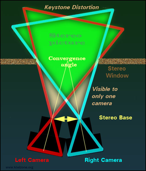
Stereoscopic macro photography uses convergence to avoid cutting off lateral parts of the two images while setting the stereo window.
Convergence allows full frame images, filling the wide aspect ratio TV and Computer screens, which are standard today.
Perspective correction during post processing is essential, but easily done with modern soft-ware.
Using convergence, the stereo base can be set accurately with NO MATHS!
Bercovitz FormulaThe Bercovitz formula works in all stereo situations but it becomes cumbersome in macro photography because the measurements are hard to make, especially when toe-in is used. The distance to the object (n) can be difficult to measure because you do not always know where the first nodal point of the lens is placed, especially if there is internal focusing, or you are using supplementary lenses. I find it is better to compute n from the chosen reproduction ratio (camera magnification) and lens focal length. n = F ( 1 + 1 / R ) n = nearest distance From the De Marzio formula, the maximum distance allowable in the stereo image at macro distances is twice the nearest distance: m = 2 n Otherwise the disparity on the final image will be too much for the average person in the audience. (This is a simplification, which fails at high magnifications.) Measuring the stereo base when the lenses are turned in becomes a problem, as it must be done at the level of the first nodal point. Not the distance between the cameras, since the lens(es) are closer than the camera bodies. (see the diagram). |
Camera rotationIf you are to toe in the camera, how much should it be angled in? It is nice to have round things looking round in 3D, especially in the macro range where scientific or medical decisions may be made based on how objects look. The perceived depth of a sphere should be equal to its width. Macro photography is where my experiments on stereo roundness really began. The parameters derived there apply at all sizes, right down into the stereo microscopy range. (Base for perfect roundness of 1) = Br1 = n i / V Viewing distance, VRoundness varies with the final viewing distance, so it is necessary to decide that first. 1 meter Computer screen Large screens (lecture theatre or pub) demand a small stereo base , which strictly needs to be computed separately for different viewing distances. That gets a bit cumbersome and depends on your obsessiveness or how critical the result will be. Nearest object, nHard to measure at macro distances, especially on an internally focusing lens with a built-in lens hood. So compute n: n = F ( 1 + 1 / R ) This is one of the standard thin lens equations. |
Macro Perfect Roundness equation, using easily measured parameters.
|
Di Marzio base from magnification equation:B = F ( 1 + 1 / R)/ 15 Frank Di Marzio derived this equation when I asked him to compute stereo base in terms of magnification marked on a macro lens (R). He set up the equation to work when the maximum distance was equal or less than twice the nearest (m < 2n), which is usual in 3D macro photography. This equation ends up as his n/15 rule for macro stereo, instead of the usual n/30 rule for standard stereo photography. (He did not derive it that way, however). Where does the constant, 15, in the Di Marzio equation come from?If the viewing distance is 1 meter, So the late Frank Di Marzio set up his macro 3D equation for perfect roundness at a viewing distance of 1 meter. (He did not use the term "roundness," which was not invented then.) Since Frank's equation only applies when m<2n, that also applies to the Wattie equation. P in the Bercovitz equationn/15 works fine in the close-up range, but in the macro range, if n/15 is desired for correct roundness when viewed on a computer and m is set at 2n, Parallax can rise above the recommended 1.2mm, getting worse as magnification rises. This may be acceptable on a small computer screen, as the maximum deviation will also be small. However, if Parallax is getting painful for some of your audience, the cure is to The computation can be done by iteration of the Berkovitz formula, checking the roundness by the Wattie method, then reducing maximum distance (m) until roundness is acceptable at n/15. Thickness can be dropped by removing any background objects, because even if they are out of focus, they cause an unacceptable deviation. If m cannot be reduced, then you will just have to reduce the stereo base and accept a slightly flat stereo. |
Double riggingAnother method for reducing the thickness of close-up subjects, first mentioned in edition 1 of this web site, is to move the background sideways between the two pictures so that it ends up just behind the main subject on the stereoscopic final image. Chroma screenThis sort of thing is more often done with blue-screen photography.
Out of focus plain background colour is of course no problem because there is nothing for the eyes to fix on. This remark does not apply if there is a variation in light intensity across the background, unless that variation is strictly in the vertical direction only. Otherwise you get a bright piece of background for one eye and a dimmer background for the other, which causes retinal rivalry. The disconcerting change in background brightness causes discomfort for the audience. The same problem of backgrounds having different brightness is a worry in anaglyphs. The simple "full colour anaglyph" is a major offender, because blue sky comes out very dark in the red channel (left eye). A "half colour anaglyph" is better because some of the blue and green luminosity is inserted into the monochromatic red channel, reducing the retinal rivalry by making blue sky and green leaves equal in luminosity for the two eyes. Other recipes, like the DuBois process, produce even better equalisation of luminosity. The colour is wrong, but colour is badly messed up in anaglyphs anyway and you do not want to add in retinal rivalry. |
Roundness from convergence angleIn the roundness section, you might have missed the stereo base stated as an angle. So there it is -> This example is using a stereo base of 65mm, which is the usual inter-ocular distance for adults. The distance to the stereo window is 1 meter, which is comfortable viewing on a computer screen. That means, if you toe in the cameras by 3.7 degrees, that will give the correct roundness for viewing from 1 meter. Alternatively, you could keep the camera still and rotate the subject by 3.7 degrees. This rotation method for deciding the stereo base avoids mathematics, as it works at any magnification. There are two methods I use for this rotation method. One is useful in the field while the second works in the studio: Rotate in the field
This sequence gives a rotational base of 4 degrees, suitable for viewing in stereo at just under a meter. Rotate in the studio
This sequence gives a macro 3D image suitable for viewing at 1 meter. Both of these methods can be combined with focus stacking. Viewing on bigger screensIt is not the size of the screen that matters really, but how far you sit from the screen. Anyway, large screens are normally viewed from further away, so bigger screens demand a smaller stereo base, which translates as a smaller toe-in angle.
|
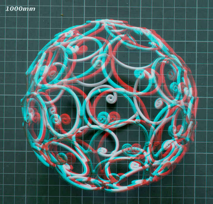
Roundness in 3D is very sensitive to how far the camera was from the ball and the stereo base
Use radians to measure toe-in angleThe toe in angle is better measured in radians because the tangent or sin of a small angle is the same as the angle in radians. angle in radians = 1 / nearest
* Di Marzio's 1/15 rule for close-ups, which applies to seeing good roundness on a computer from 1 meter, if your eyes are 65mm apart. Radians give a quick way to get the correct angle when rotating a circular stage. Turn the stage by measuring how far a point on the stage rim moves by: (Angle in radians) * (radius of the stage) |
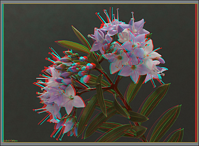 |
New Zealand Hebe.Photographed on a rotating stage, 0.067 radians between the two pictures. Focus stacking used. |
Focus stackingMacrophotography of scientific objects requires sharp focus all over the image. The aim is to have a photograph similar to a scientific drawing, with no blurred zones. DOF. Lenses cannot achieve sharpness in depth, especially in the macro or telephoto ranges. There is always a depth of focus (DOF) and objects in front or behind the ideal depth range are increasingly blurred. Diffraction of light is a problem. DOF can be increased by using a small aperture (f-stop) Pin-hole photographs are never sharp because light passing through a tiny hole gets diffracted and the image s made up of a lot of tiny, superimposed circles (if the pin-hole is circular). Images taken beyond the diffraction limit of a lens are also blurred, which becomes worse as the f-stop rises (which means the aperture is getting smaller). A scanning electron microscope (SEM) has the ideal depth of focus, with nothing blurred. It is made by scanning an electron beam over the tiny object and recording the back scatter electrons, gradually building up the image in a raster. Normally the object is coated with a thin metal layer (often gold), to allow good electron reflection and prevent the specimen becoming electrically charged. SEM images are grey but can be coloured artificially. Macrophotography using light can have a large depth of focus (DOF) so that it looks rather like a scanning electron microscope image. The colours are true, although the magnification and resolution is much less. Enhanced depth of focus with light images is achieved by taking multiple images, each with a very small DOF, but without diffraction. The diffraction limit is set by the f number. It depends on the degree of magnification and the pixel size of the receptor. Each image is taken with the camera (or the specimen) moving closer, in steps (as with a stepper motor). The stack of very sharp images is then fused into one image using image stacking software. The thickness of each slice is usually arranged as 75% of the DOF. Tables are available for setting up slice thickness in focus stacks and avoiding diffraction blur (Savazzi). |
Bokeh"Artistic" photographers claim a limited depth of focus (DOF) is a good thing (making a virtue of optical necessity). I rebelliously take the opposite view: perfect, diffraction-free focus throughout the depth of the object is my aim, but seldom achieved because cameras are not up to it. In real life we, or I at least, are not impressed by blur and are likely to make a visit to the optometrist to have our spectacles corrected. Artistic types (who are to be found in photographic clubs and in cinema studios) further claim out of focus areas can be good or even better depending on bokeh or boke (a Japanese word). Out of focus spots should not have sharp edges, but aim for circles with an ill-defined edge, so that the background does not have an obvious texture. Some claim that only the background should show bokeh and anything close by should be well focused (Ken Rockwell). This is called "clever use of selective focus," which I, as a rebel, claim is talking bollocks since this bokeh is a defect of camera lenses, not a virtue. What makes good bokeh is a matter of opinion and the discussion makes little sense in scientific photography as the "best" bokeh comes from a poor quality lens showing spherical aberration, which is not likely to give a nice sharp image where it is supposed to be in focus. In stereoscopic macro photography, nothing should be out of focus, but if there must be any blur, it should not be intrusive. This requirement is much the same as asking for good bokeh. The background must not contain sharp edges, such as the circular edge of an out of focus point source or high luminosity specular reflection. This is where diffuse lighting helps yet again. Of course, out of focus parts of an image pair can be stereoscopic, as in zone-plate stereo. Blurred 3D can be effective. "Good" bokeh can be set up in a focus stack: The background, which has not been included in the stack, is severely out of focus. To correct this, the background image is taken at the end of the stack. The last image is taken with the lens stopped right down, increasing the exposure time, so there is lots of diffraction blur, but improved over-all focus. Diffraction gives a good bokeh, according to me. But I am not a photographic artist. |
Solar rotation for stereoscopyThe rotation method for stereoscopy works for the biggest down to the smallest of subjects. BUT when taking the stereo pair, you must decide first how far from the screen you are are going to sit while viewing the result.
This stereoscopic image of the sun was taken by the Solar Dynamics Observatory. 10 hours represents a huge stereo base, but the largest object in the solar system follows the Variable Viewing Distance rule for stereoscopic roundness. Move backwards and forwards, while seeing in 3D through anaglyph glasses and the sun's roundness will change. As you can see, this image is set up for viewing on a computer or in a book. Stereo pictures are also taken of the moon and Jupiter using rotation for the stereo base. |